Multi-Sensor Maritime Monitoring - From Vessel Edge to Shore Operations
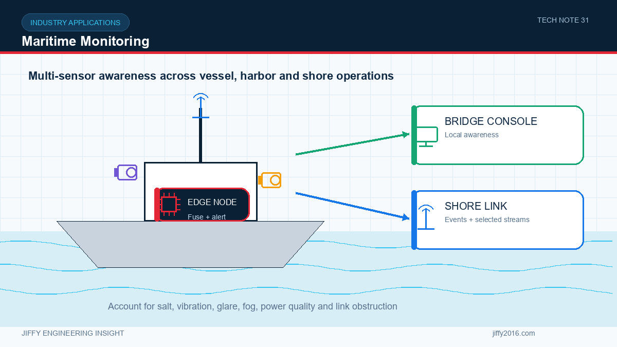
Quick answer: A maritime monitoring system combines visible and thermal imaging with onboard edge processing so that useful awareness remains available despite changing shore connectivity. Camera placement, corrosion protection, vibration, glare, fog, salt contamination, power quality and antenna obstruction must be considered together. The network should prioritize alarms, health and selected evidence while retaining appropriate data locally.
Maritime environments are visually and electrically difficult. Glare, haze, darkness, spray and continuous motion can reduce image quality, while salt, vibration and long service intervals challenge the hardware. Communications also change with route, antenna height and nearby structures.
A robust architecture performs essential image handling and event processing onboard. Shore connectivity adds coordination and records, but it should not be the only path to a useful local view.
- Key Takeaways
- Combine visible and thermal imaging because the two channels provide different evidence.
- Keep display, event detection and buffering available onboard.
- Test camera placement for vibration, spray, glare, self-heating and vessel obstruction.
- Prioritize alarms and health data over continuous high-rate transfer.
- Validate corrosion protection, connectors, power quality and link recovery.
- Select Sensors by Detection Task
- Camera Placement on a Vessel
- Occlusion by masts, rails, equipment and changing payload
- Vibration and movement at the mounting point
- Spray, rain and salt deposits on the optical window
- Direct sun, reflections and nighttime lights
- Exhaust, hot surfaces or other thermal interference
- Cable length, connector protection and maintenance access
- Onboard Edge Processing
- Vessel and Shore Communications
- Power and Environmental Validation
- High and low operating temperature
- Humidity and condensation behavior
- Vibration and connector retention
- Salt exposure appropriate to the product requirement
- Repeated power cycles and controlled shutdown
- Lens-window contamination and cleaning method
- Long-duration simultaneous processing and radio use
- Data and Operator Design
- Frequently Asked Questions
- Does thermal imaging work through fog?
- Should visible and thermal images always be fused?
- What should be stored onboard?
- What is the biggest installation risk?
- Conclusion
Visible cameras provide texture, color, markings and contextual detail. Thermal cameras respond to temperature contrast and can remain useful in low visible light, although performance still depends on atmospheric conditions, lens contamination and target contrast.
The sensor combination should follow the task. Define the target size, distance, relative movement and environmental limits. Then select resolution, field of view and mounting position. A narrow lens may provide more target detail but reduce search coverage; a wide lens may cover the scene while producing too few pixels on a distant target.
If visible and thermal images are presented together, synchronize timestamps and calibrate their relative geometry. Operators should understand when an overlay is approximate and when it is measurement-grade.
The final location affects both image and serviceability. Consider:
Use strain relief and corrosion-resistant installation practices appropriate to the environment. A sealed enclosure still needs a strategy for condensation and heat transfer.
The edge platform can acquire multiple sensors, align timestamps, enhance images, run analytics, encode streams and retain event clips. It also supports a local bridge or operations display.
Processing should be sized for all active functions. Test visible and thermal streams together with encoding, display, recording and network transfer. Record dropped frames, processing latency, memory use and temperature over a long-duration run.
When analytics are used, evaluate them against sea clutter, reflections, birds, weather and moving backgrounds. Thresholds that work in a calm harbor may behave differently offshore.
The communication path may change as the vessel moves or as line of sight is obstructed. Define the information priority:
1. Critical alarm and safety-related status
2. Device health and location metadata where applicable
3. Event image or short event clip
4. Operator-requested live stream
5. Background transfer of stored data
The onboard system should buffer data during an interruption and synchronize it without blocking current alarms after the link returns. Record reconnect time and application recovery, not only radio signal level.
For RF links, antenna height, polarization, cable loss and vessel structure all affect coverage. Check coexistence with other onboard radios and confirm applicable regional requirements.
Power rails on a vessel may include switching noise, transients and ground-potential differences. Confirm the actual supply range, bonding and protection requirements for the installation. Keep sensitive camera and RF grounds controlled and avoid unintended current paths through signal cables.
Environmental validation should include:
More video is not automatically more awareness. The interface should make it easy to identify sensor source, time, zoom level and system health. Alarms need enough context for verification without overwhelming the operator.
Maintain configuration and firmware records for every device. Remote update procedures should include bandwidth limits, failure recovery and a known-good rollback state.
Thermal imaging may provide useful contrast in some low-visibility conditions, but fog, humidity, distance and wavelength still affect performance. Validate the required detection task in representative conditions.
No. Side-by-side display may preserve clarity. Fusion is useful when registration is calibrated and the operator or algorithm benefits from combined context.
Retain the evidence needed during network interruption, such as event clips, key frames, health logs and selected continuous recording. Size storage from bitrate and outage duration.
Ignoring the final structure. Vessel metalwork, heat sources, vibration and cable routes can change camera and antenna performance significantly.
Effective maritime monitoring depends on complementary sensors, dependable local processing and communications that degrade gracefully. The design must remain observable and maintainable under real environmental conditions.
Jiffy supports visible and thermal camera modules, edge computing, RF modules and wireless video integration. Contact support@jiffy2016.com for technical evaluation and customization discussions.
Discuss your system requirements with Jiffy
market@jiffy2016.com | www.jiffy2016.com
Subscribe to Our Newsletter
Your Email*
*Country*
*Verification code