Designing Rugged Vehicle-Mounted Vision and Wireless Systems
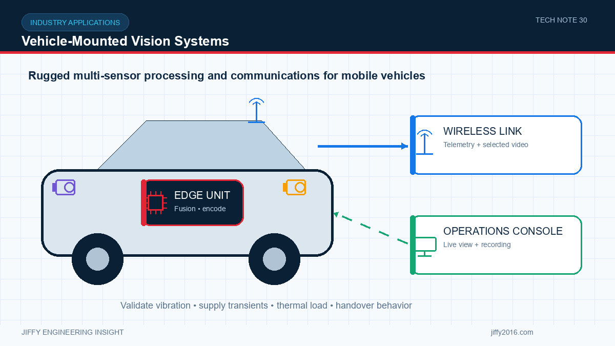
Quick answer: A vehicle-mounted vision system must coordinate camera placement, onboard edge processing, power conditioning, thermal design and mobile wireless connectivity. Essential sensing and local decisions should continue during network interruption, while selected video, status and diagnostics are transmitted to operations. Validation should include vibration, supply transients, temperature, antenna shadowing, handover and simultaneous multi-camera load.
Vehicles create a demanding environment for cameras, edge computers and RF equipment. The system moves through changing illumination and radio coverage while experiencing vibration, electrical transients, limited mounting space and wide temperature variation.
Reliable operation comes from designing the mechanical, electrical, imaging and communication paths together. A bench demonstration is only the beginning; the final vehicle installation is the real system.
- Key Takeaways
- Keep essential sensing and processing onboard so that basic operation does not depend on continuous connectivity.
- Select camera positions from target coverage, occlusion, contamination and service access.
- Protect electronics from crank, load, motor and switching transients in the vehicle power system.
- Test antenna performance after the complete vehicle and payload are assembled.
- Validate all cameras, AI, encoding, recording and radio functions concurrently at temperature.
- Define the Operational Image Requirement
- Onboard Edge Architecture
- All camera inputs at production resolution and frame rate
- Image conversion, scaling and synchronization
- AI inference for every required stream
- Video encoding and local preview
- Event recording and storage writes
- Wireless transmission and device management
- Vehicle Power Is Not a Laboratory Supply
- RF Link and Antenna Integration
- Mechanical and Thermal Design
- Recommended Validation Plan
- Frequently Asked Questions
- Should all video be sent to the control center?
- Where should the wireless antenna be installed?
- What causes intermittent camera faults on vehicles?
- Is an enclosure rating enough for ruggedness?
- Conclusion
Vehicle-mounted cameras may support situational awareness, remote supervision, inspection, recording or embedded analytics. Each function has a different requirement for field of view, frame rate, latency and retained evidence.
Map every camera to a target zone. Record the closest and farthest useful distance, smallest relevant feature and expected vehicle speed. Include blind zones caused by the body, tools or payload. If the camera is exposed, consider water, dust, mud, cleaning and lens-window replacement.
For wide lighting variation, test direct sunlight, shadow transitions, headlights, low illumination and reflective surfaces. Exposure and gain settings that work while stationary may create motion blur at operating speed.
The edge computing platform can receive several camera streams, synchronize or timestamp them, run AI models, encode video and store event data. Local processing reduces network load and preserves function when the wireless link is unavailable.
Size the platform from the peak simultaneous workload:
Measure camera-to-result and camera-to-display latency after the system reaches thermal equilibrium. A platform can pass a short test and later reduce clock speed as internal temperature rises.
The electrical system can experience startup dips, alternator variation, inductive loads, reverse connection and switching noise. Determine the voltage range and transient environment for the target vehicle instead of assuming a nominal 12 V or 24 V rail is stable.
A robust input stage may include reverse-polarity protection, transient suppression, filtering, controlled startup and hold-up appropriate to the application. Measure voltage at the edge processor and radio during vehicle startup, acceleration and operation of high-current accessories.
Use defined shutdown behavior so that recording and storage are not corrupted when vehicle power is removed. If a backup source is used, specify which functions remain active and for how long.
The vehicle body, roof accessories, payload and nearby people can change the antenna pattern. Position the antenna with the required ground reference and clearance. Keep RF cable runs short where possible and secure them against vibration and abrasion.
If multiple antennas are installed, check isolation and simultaneous transmit behavior. A high-power nearby transmitter can desensitize another receiver even when the systems use different frequencies.
Field testing should follow the actual route. Record link quality, application latency, video interruptions, handover events and reconnect time. Include locations where the vehicle turns, passes large metal structures or enters covered areas.
Connectors, circuit boards, heat sinks and cables all experience vibration. Use locking connectors, strain relief and mounting points appropriate to the expected profile. Verify that camera calibration remains stable after vibration and repeated temperature cycles.
Thermal design must consider solar load, sealed housings and stationary operation. When the vehicle stops, cooling airflow can drop while cameras, edge processing and radios remain active. Test that condition explicitly.
Avoid mounting a temperature-sensitive camera directly beside a major heat source. If thermal imaging is used, prevent heat from the vehicle or enclosure from contaminating the measurement scene.
1. Verify every camera’s image quality and field of view on the final vehicle.
2. Run all acquisition, AI, encoding and recording functions together.
3. Test startup, voltage dip, controlled shutdown and repeated power cycles.
4. Perform vibration and connector-retention checks.
5. Run the system at high and low expected temperature.
6. Measure radio performance along the complete route.
7. Force network loss and confirm defined local behavior.
8. Confirm event data and configuration survive controlled faults.
Not necessarily. Many systems send status and selected streams while keeping high-quality or event recording onboard. The policy should follow operational and network requirements.
Use a location with suitable clearance, ground reference and cable routing. The best position depends on the vehicle geometry and target coverage, so verify the complete installation.
Common causes include connector movement, supply dips, cable damage, electromagnetic noise, overheating and software recovery behavior. Log power, temperature and interface errors together.
No. Sealing does not prove vibration tolerance, connector retention, thermal performance, corrosion resistance or optical-window durability.
Vehicle-mounted vision and wireless systems require more than rugged-looking housings. They need measured performance across imaging, computing, power, thermal, mechanical and mobile RF conditions.
Jiffy supports compact camera modules, wireless video links, RF modules and edge computing platforms for vehicle and mobile equipment integration. Contact market@jiffy2016.com to discuss interfaces and system requirements.
Discuss your system requirements with Jiffy
market@jiffy2016.com | www.jiffy2016.com
Subscribe to Our Newsletter
Your Email*
*Country*
*Verification code