Wireless Vision and Edge Computing for Autonomous Mobile Robots
Quick answer: An autonomous mobile robot should keep perception and safety-critical decisions onboard while using the wireless network for supervision, job dispatch, status and selected video. The architecture must be validated for multi-camera load, roaming, interference, power transients, thermal limits and controlled recovery. Reliable performance depends on coordinating cameras, edge computing, antennas, network design and fleet software rather than optimizing one component alone.
Autonomous mobile robots operate at the intersection of machine vision, embedded computing and industrial wireless networking. They must perceive the environment locally, make decisions within a predictable time and remain connected as they move through areas with racks, machinery, doors and changing radio conditions.
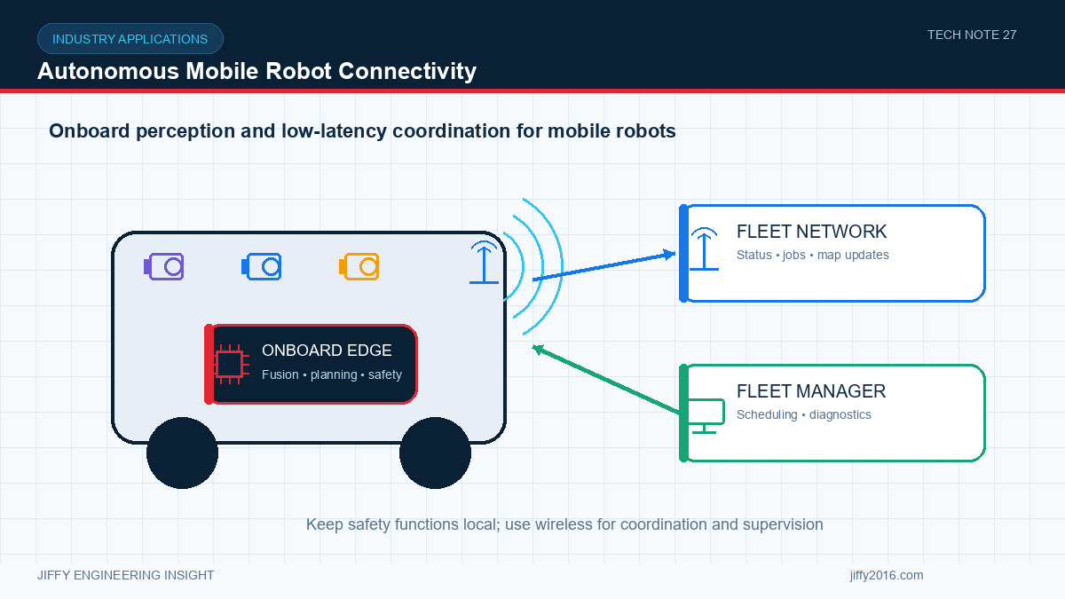
The best architecture separates functions by their tolerance for delay and connection loss. Local functions remain dependable even when coverage changes; network functions improve coordination and visibility without becoming a single point of failure.
- Key Takeaways
- Keep obstacle perception, motion control and essential safety behavior local to the robot.
- Use wireless connectivity for missions, maps, status, diagnostics and selected video.
- Budget all camera and AI pipelines at the same time, including memory and thermal load.
- Design antenna position and network coverage around the robot’s complete route.
- Test roaming, interference and recovery while the robot is moving and carrying its normal workload.
- Divide Local and Network Functions
- Multi-Camera Edge Processing
- Frame acquisition continuity for every camera
- Camera-to-result latency at peak workload
- Inference rate and worst-case execution time
- Memory use and memory bandwidth
- Encoder and network output rate
- Processor temperature and throttling status
- Recovery after a camera or application restart
- Wireless Network Design for Movement
- Coverage at the robot antenna height
- Handover time between coverage cells
- Packet delay and jitter during handover
- Interference when multiple robots transmit
- Uplink capacity for status and video
- Recovery after a short or extended outage
- Antenna Integration on the Robot
- Power and Thermal Behavior
- A Practical Validation Sequence
- Frequently Asked Questions
- Should live video be transmitted continuously?
- Is low average latency sufficient?
- Can the radio antenna remain inside the metal enclosure?
- What should happen when wireless connectivity is lost?
- Conclusion
The first architecture decision is not the radio frequency or camera resolution. It is the functional boundary between the robot and the fleet system.
Functions that require deterministic response should remain onboard. These can include sensor capture, obstacle detection, localization support, immediate motion decisions and local fault handling. Functions that benefit from shared information can use the network: job assignment, map distribution, fleet traffic coordination, status reporting, maintenance logs and operator video.
This separation creates a clear rule: loss of the network may reduce fleet efficiency, but it should not create undefined robot behavior. The expected response to network loss—slow, stop at a safe location, complete a local task or reconnect—must be defined and tested.
A mobile platform may combine forward, rear, side or overhead cameras with depth, thermal or other sensors. Each stream consumes interface bandwidth, memory bandwidth and processing time before an AI result is produced.
Calculate the raw input rate from resolution, pixel format and frame rate. Then include resizing, color conversion, inference, encoding, display and recording. These operations often overlap. Average processor utilization does not reveal short bursts that cause buffer overflow or delayed control data.
Useful validation metrics include:
If sensors must be fused, use a shared trigger or accurate timestamps and validate the maximum time offset under load.
A stationary link test does not represent a moving robot. Antenna orientation changes relative to access points, the vehicle body can shadow the signal, and nearby objects create multipath. Network design should use the real route and traffic conditions.
Start with a route map. Mark narrow aisles, corners, elevators, doors, loading zones and areas where other equipment can obstruct the path. Measure signal quality and packet behavior while the robot moves at operating speed.
The network should be evaluated for:
RSSI alone is not enough. Record end-to-end application behavior, including command latency, retransmissions, video freezes and the time required to restore normal service.
The antenna must coexist with cameras, processors, motors, power converters and a metal chassis. Place it away from high-current switching paths and give it the clearance required by its design. Route RF cables with controlled bends and secure connectors against vibration.
Two antennas placed close together can interact even when they serve different radios. Check isolation and simultaneous operation. The enclosure, battery, payload and installed accessories may change the radiation pattern, so the final configuration should be tested rather than only the development prototype.
Robot batteries and motor drives create a dynamic electrical environment. Acceleration, braking and actuator operation can produce supply dips or transients. Cameras, radios and edge processors should be tested during these events.
Build the power tree with defined startup order, rail margin and protection. Measure voltage at the load, not only at the battery. A radio transmit burst or high AI load can expose a weak converter or cable path.
Thermal design must cover low-speed or stationary operation, when airflow is limited. Run all cameras, AI models, video encoders and radios together at the highest expected ambient temperature. Confirm that processing rate and latency remain stable after temperature reaches equilibrium.
1. Validate each camera and interface independently.
2. Run all camera pipelines concurrently on the edge platform.
3. Add the production AI model and recording workload.
4. Test the radio under controlled attenuation and interference.
5. Install the system on the final robot and repeat power and thermal tests.
6. Drive the complete route while logging network and application metrics.
7. Force network interruption, camera faults and application restarts.
8. Confirm the robot and fleet system return to a known state.
Only if operations require it and the network is sized accordingly. Many systems send metadata and low-rate preview video normally, then request a higher-quality stream for an event or remote diagnosis.
No. Mobile systems are affected by worst-case delay and jitter. Measure latency distributions during movement, handover and network load.
Usually this reduces performance or creates direction-dependent coverage. Use an antenna location and enclosure design that provide the intended RF clearance, then verify it on the complete robot.
The behavior must be explicitly defined by the system safety and operations requirements. The robot should enter a known mode, continue only permitted local functions and reconnect through a controlled process.
A reliable mobile robot is not simply an AI computer connected to a radio. It is a coordinated system in which sensing, local decisions, power, thermal design and mobile connectivity have measurable interfaces and failure behavior.
Jiffy works with equipment manufacturers and system integrators on camera modules, RF connectivity, wireless video and edge computing platforms. Contact support@jiffy2016.com for technical integration discussions.
Discuss your system requirements with Jiffy
market@jiffy2016.com | www.jiffy2016.com
Subscribe to Our Newsletter
Your Email*
*Country*
*Verification code