From Camera to Edge - How to Plan a Testable Wireless Vision System
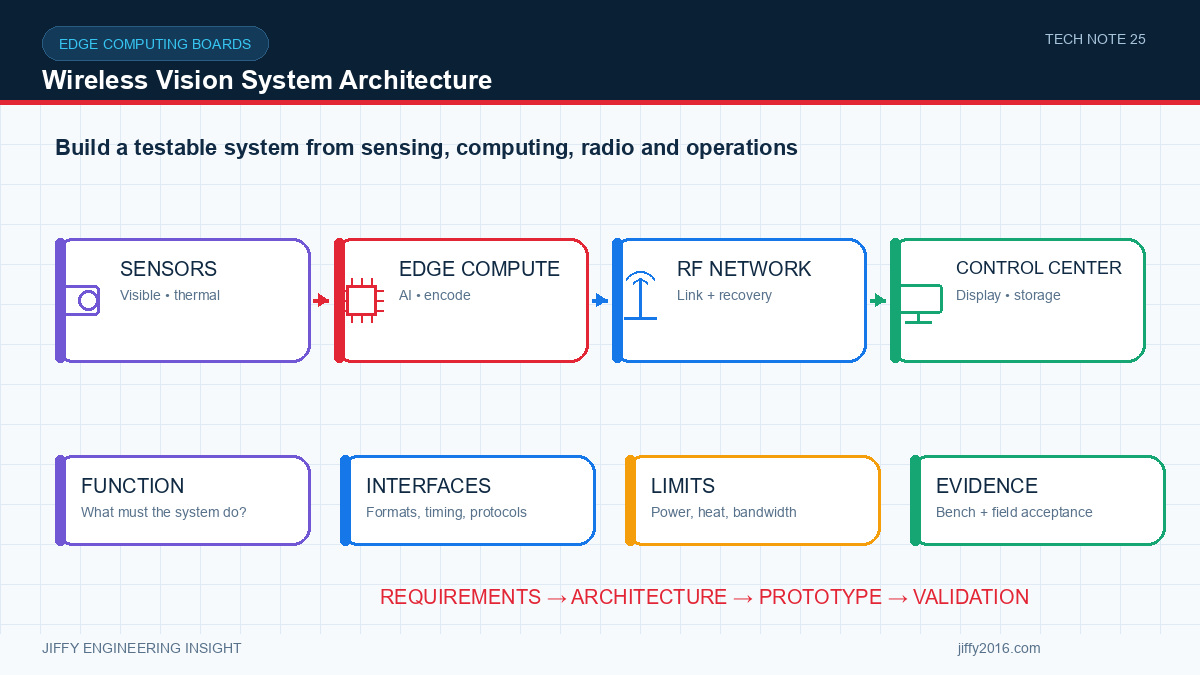
Quick answer: A dependable wireless vision system is built by defining the task first and validating the complete path from image capture to operator or machine response. This guide explains how to align cameras, RF links, edge computing, power, thermals and recovery behavior around measurable requirements.
A wireless vision system is more than a camera connected to a radio. It is a complete path that begins with light or temperature at the target and ends with a decision, alarm, recording or control action. Every stage—image capture, processing, compression, transport, decoding, inference, display and storage—contributes to performance and reliability.
Planning the architecture as one system helps prevent a common integration problem: every component appears to meet its own specification, but the assembled product does not meet the application requirement.
- Key Takeaways
- Define a measurable observation or inspection task before selecting hardware.
- Map the complete data path, including formats, buffers and ownership.
- Size the wireless link from real application traffic and site conditions.
- Run camera, encoding, AI, storage and RF functions together.
- Turn system requirements into repeatable acceptance tests and version records.
- 1. Define the decision the system must support
- 2. Map the complete data path
- Input and output format
- Average and peak data rate
- Buffering and expected latency
- Clock or synchronization requirement
- Error and recovery behavior
- Hardware and software owner
- 3. Select cameras around the target and environment
- 4. Size the wireless link from real traffic
- 5. Match the edge platform to the complete workload
- 6. Design interfaces, power and thermals together
- 7. Validate in controlled stages
- 8. Control versions and evidence
- Conclusion
- FAQ
- Which subsystem should be selected first in a wireless vision project?
- Why should video, AI and wireless transport be tested together?
- What makes a system test repeatable?
- CTA
Begin with the operating task, not a list of components. Describe what a person or algorithm must detect, how quickly the information is needed and what happens after detection.
Examples include confirming equipment position, reading a gauge, finding a thermal anomaly, identifying an obstruction or recording a process step. Each task creates different requirements for resolution, frame rate, field of view, low-light performance, temperature sensitivity, latency and recording quality.
Write measurable acceptance criteria where possible. “Clear video” is subjective. “The operator can identify a specified target at the defined distance and lighting condition” creates a testable requirement.
Draw the path from every sensor to every destination. Include camera interfaces, image processing, scaling, encoding, RF transport, Ethernet or serial links, decoding, AI inference, display, storage and return control data.
For each stage, record:
This map reveals format conversions, memory copies and shared interfaces that are easy to overlook. It also shows where a fault can be detected and how the system should recover.
Camera selection should connect target size, distance and field of view to the required image detail. Confirm resolution, sensor size, pixel size, lens, frame rate, exposure range, dynamic range, interface and cable constraints.
For thermal imaging, also define the expected temperature range, target surface, viewing angle, working distance and whether the task requires absolute measurement or relative contrast. If visible and thermal sensors are combined, decide whether the application needs side-by-side display, approximate overlay or calibrated registration.
Mounting, vibration, contamination, protective windows and enclosure temperature must be considered with the optics. A strong laboratory image does not guarantee stable results after the sensor is installed in the final equipment.
Calculate the combined application traffic instead of relying on the radio’s physical-layer rate. Include video streams, bitrate peaks, protocol overhead, retransmissions, telemetry, control traffic, logging and software updates.
Define acceptable end-to-end latency and recovery time. Camera exposure, encoding and buffering can contribute as much delay as the radio. Test high-motion and high-detail scenes because variable-bitrate encoders may create short traffic peaks that do not appear with a static image.
Build a link budget using transmit power, antennas, cable losses, receiver sensitivity, path loss and a realistic fade margin. Antenna height, orientation, nearby metal, obstruction and interference should be evaluated in the intended operating route or site.
An edge platform must sustain camera input, image signal processing, format conversion, video encoding, AI inference, storage and networking at the same time. Processor or NPU headline performance alone does not describe application throughput.
Record the camera configuration and run the complete workload with representative scenes. Monitor frame rate, inference latency, memory use, queue depth, dropped frames, network throughput, storage behavior and temperature.
For multi-camera applications, define synchronization and camera identity. Verify behavior after cold start, restart, cable reconnection and long continuous operation. The system should detect a missing camera without silently changing device assignments.
Confirm connector pinout, voltage levels, protocol settings, boot states and power sequencing for every boundary. Measure power at the device under real transmit and processing loads, including start-up and short current peaks.
Thermal design must reflect the final enclosure, mounting orientation, ambient temperature and nearby heat sources. Test RF transmission, video encoding and AI processing together because the combined workload may expose throttling or instability that isolated tests miss.
Protection and monitoring should have defined responses. Decide when the system should warn, reduce load, restart a subsystem or require manual recovery.
A practical validation sequence includes:
1. Interface baseline: confirm cameras, radio, edge platform and control interfaces at short range.
2. Full workload: run all video, AI, storage and network functions together.
3. Controlled impairment: introduce attenuation, obstruction, traffic peaks and power interruptions.
4. Representative environment: test the intended route, antenna positions, lighting, target distance and temperature.
5. Long-duration operation: monitor thermals, memory, frame loss, reconnection and configuration retention.
6. Production baseline: record the approved hardware, firmware, models, settings, cables and test method.
The result should be a repeatable acceptance test, not a one-time demonstration.
Keep a system record that links hardware revision, firmware, operating system, drivers, AI model, radio settings, camera configuration and test results. When performance changes, this record makes it possible to identify whether the cause is hardware, software, configuration or environment.
Photographs of the setup, antenna positions and cable routing are useful evidence. Distance or throughput numbers should always include the configuration and test conditions that produced them.
A successful wireless vision product is defined by the behavior of the complete path from target to decision. The most effective development process aligns imaging, RF transport, edge processing, interfaces, power, thermals and recovery around measurable acceptance criteria.
Jiffy can help review the architecture, identify suitable building blocks and define an evaluation plan for industrial wireless and vision systems.
Start with the target and required decision. Those requirements define imaging detail, latency, processing, transport, power and environmental needs, which can then be mapped to hardware.
They share processing, memory, power and thermal resources. Isolated tests can miss traffic peaks, frame loss, throttling and recovery interactions that appear only in the complete workload.
Use measurable acceptance limits and record hardware, firmware, models, settings, antennas, cables, scenes, route, temperature and impairment method for every result.
Title: Turn Your System Requirements into a Validation Plan
Primary button: Discuss Your Project
Secondary button: Explore Related Products
Discuss your system requirements with Jiffy
market@jiffy2016.com | www.jiffy2016.com
Subscribe to Our Newsletter
Your Email*
*Country*
*Verification code