RF Layout and Antenna Placement Inside Industrial Equipment
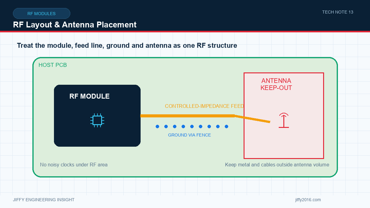
Quick answer: Good RF module integration keeps the RF path short and controlled, provides the required ground reference, isolates switching and high-speed noise, preserves antenna clearance and validates the antenna in the final enclosure. Layout, cable routing, mounting and enclosure materials must be reviewed together because each can change loss, matching and radiation pattern.
An RF module can perform correctly on an evaluation board and poorly in the host product when its antenna path is routed beside a switching regulator, the antenna is placed behind metal or the ground reference is interrupted. RF performance depends on physical implementation.
- Key Takeaways
- Follow the selected module’s reference layout and keep-out guidance.
- Maintain controlled impedance and a continuous reference plane.
- Separate RF and antenna regions from digital and power noise.
- Treat enclosure, display, battery and cables as part of the antenna environment.
- Validate the complete production assembly in representative orientations.
- Place the module early
- Control the RF path
- Grounding and shielding
- Antenna clearance
- Cable routing
- Validate the installed antenna
- Layout review checklist
- Module location and keep-out confirmed
- RF trace geometry matches the layer stack
- Continuous reference plane maintained
- Power filtering and decoupling placed correctly
- Noise sources separated from RF and antenna areas
- Antenna clearance documented in 3D assembly
- Cable type, length and route controlled
- Shield and chassis ground strategy reviewed
- Test points do not create unacceptable RF stubs
- Final assembly included in validation
- FAQ
- Can the antenna be tested outside the enclosure?
- Is a longer antenna cable better than placing the module near the antenna?
- Can shielding solve digital interference?
- Conclusion
Choose the module location before the board is crowded. Consider antenna path, heat, service access, connector orientation and noisy circuits. A late placement decision can force long RF traces or antenna cables and create unnecessary transitions.
Keep clocks, memory buses, display interfaces, motors and switching nodes away from sensitive RF and antenna areas where practical.
Use the required impedance, trace geometry, layer stack and reference plane. Keep the path short and minimize vias, connectors and adapters. If transitions are necessary, document them and include their loss in the link budget.
Do not place gaps in the ground reference beneath the controlled RF trace unless the selected design guidance explicitly requires a different structure.
Provide low-inductance grounding around the module and RF path. Stitching vias can help contain fields and connect reference planes, but spacing and placement should follow the actual board stack and frequency range.
Shielding can reduce coupling, yet a shield does not repair a poor return path or an antenna placed too close to metal. Review how the shield, chassis and connector grounds meet.
An embedded antenna needs defined clearance from copper, metal, batteries, displays, heatsinks and cable bundles. External antennas need suitable ground plane, connector access, sealing and strain relief.
The final enclosure material and wall thickness can affect matching and pattern. Even plastic assemblies may contain coatings, fasteners or internal metal that changes performance.
Keep coaxial cables away from sharp bends, crushing, hot surfaces and moving mechanisms. Control cable length and connector type. Route noisy power or high-speed cables so they do not run parallel to the antenna feed or radiating section.
Production drawings should define the intended cable route; otherwise assembly variation may create unit-to-unit RF variation.
Measure or evaluate matching and radiated behavior with the complete assembly. Test representative orientations and operating states, including display activity, processor load and transmit conditions.
Perform a short-range baseline before a route test. If two nominally identical assemblies behave differently, inspect cable routing, connector seating, grounding and enclosure assembly before changing radio settings.
That is useful as a baseline, but final approval must use the production enclosure and nearby components.
Not usually. Cable loss and routing risk increase with length. Compare module placement, heat and interface requirements as a complete design.
It may reduce coupling, but source control, return paths, filtering and physical separation remain necessary.
RF layout and antenna placement translate a module’s capability into real product performance. Control the path, ground, noise environment and enclosure, then validate the installed assembly rather than the bare module.
Discuss your system requirements with Jiffy
market@jiffy2016.com | www.jiffy2016.com
Subscribe to Our Newsletter
Your Email*
*Country*
*Verification code