Power-Supply and EMC Design for Embedded RF Modules
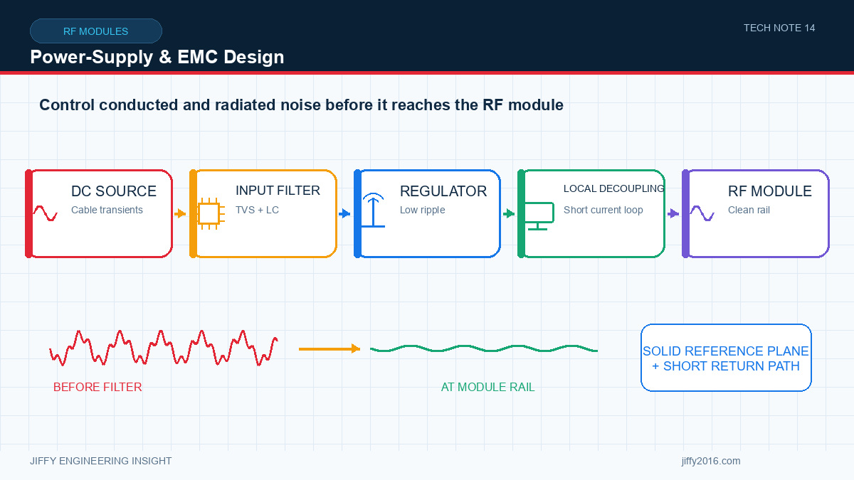
Quick answer: An RF module needs a supply that remains stable during transmit and start-up while presenting low conducted noise in sensitive bands. EMC performance depends on converter choice, decoupling, filtering, return paths, PCB layout, shielding, cables, enclosure and software operating states. Measure voltage and noise at the module under the complete product workload.
Radio current changes can disturb the host supply, while switching regulators, processors and cables can inject noise into the receiver or create unwanted emissions. Power integrity and EMC should therefore be designed and validated together.
- Key Takeaways
- Measure supply voltage at module pins during real radio activity.
- Select converters for transient response and noise, not current rating alone.
- Place local decoupling and filtering according to the module guidance.
- Control return-current paths and cable common-mode behavior.
- Test receive sensitivity and emissions with every major host load active.
- Define the radio power profile
- Choose and place the supply
- Ground and return paths
- Conducted and radiated coupling
- Firmware matters
- Validation sequence
- FAQ
- Is more capacitance always better?
- Can a metal enclosure guarantee EMC performance?
- Why does receive performance change when a display turns on?
- Conclusion
Record start-up, receive, transmit and sleep states. Include burst timing, output setting and simultaneous interfaces. Average current may hide short peaks that cause local voltage drop or converter instability.
Measure with suitable bandwidth and probe technique at the module pins. Also monitor reset and control lines during transitions.
Check input range, output accuracy, transient response, current limit and temperature derating. A converter switching frequency or its harmonics may fall near sensitive radio bands or mix with system clocks.
Keep the high-current switching loop compact. Place local capacitors and filters close to the module as specified. Long traces between the filter and load can reduce effectiveness.
Digital, power and RF currents share physical conductors. Poor return paths create voltage differences and radiated loops. Maintain a clear reference structure and avoid forcing high-current converter or motor returns through sensitive RF regions.
Review connector and chassis grounding, especially when external cables can carry common-mode current.
Noise can enter through supply, control lines, antenna path or free-space coupling. Identify likely sources such as switching converters, displays, memory, processors, motors and long cables.
Use near-field inspection, spectrum observation and controlled operating states to find correlation. Turning every subsystem off at once may hide the source relationship; change one state at a time.
Clock rates, converter modes, processor load, interface activity and radio scheduling can change interference. EMC validation should use production firmware and representative traffic.
Document any software condition required for compliance or receive performance. A later firmware change can invalidate an electrical baseline even when hardware is unchanged.
1. Verify supply start-up and radio reset behavior.
2. Measure terminal voltage and current in every radio state.
3. Observe supply noise across the required frequency range.
4. Establish a receive or link baseline with quiet host conditions.
5. Activate processors, displays, converters and external interfaces individually.
6. Run the full workload and compare degradation.
7. Evaluate external cables and final enclosure.
8. Perform formal pre-compliance or compliance testing under the defined configuration.
No. Capacitor type, placement, effective impedance, regulator stability and current loop matter. Follow a reviewed power-distribution design.
No. Seams, openings, cables, grounding and internal coupling can still dominate. Validate the final assembly.
The display interface, power converter or cable may create conducted or radiated noise. Correlate spectrum and link behavior with display states.
Power integrity and EMC define whether an RF module can maintain communication inside the host equipment. Measure at the module, activate the full workload and preserve the validated hardware and software configuration.
Discuss your system requirements with Jiffy
market@jiffy2016.com | www.jiffy2016.com
Subscribe to Our Newsletter
Your Email*
*Country*
*Verification code