Eight Questions to Answer Before Integrating an RF Module
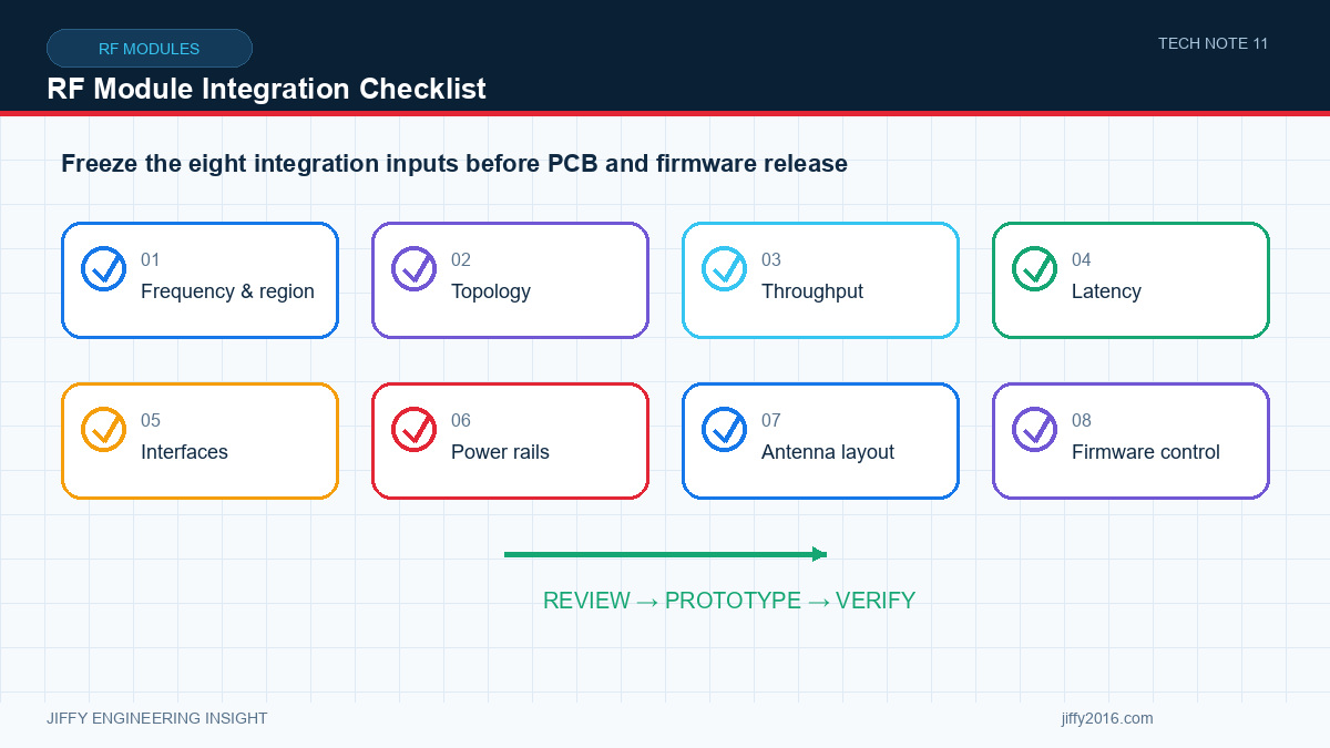
Quick answer: Before integrating an RF module, confirm the target regions, network topology, real traffic, electrical interfaces, RF path, antenna installation, power transients, thermal path and firmware-update process. Validate the module inside the final enclosure because host electronics, cables, ground structure and mechanical materials can change wireless performance.
An embedded radio module shortens development only when its electrical, RF, mechanical and software assumptions match the host product. Use these questions before fixing the PCB and enclosure design.
- Key Takeaways
- Choose the module only after defining regions, topology and traffic.
- Document interfaces at both electrical and protocol levels.
- Treat the antenna, enclosure and host PCB as part of the RF design.
- Measure power transients and temperature at the module.
- Control firmware, configuration and validation evidence through production.
- 1. Where will the product operate?
- 2. What network topology is required?
- 3. What is the real application traffic?
- 4. Which interfaces and voltage levels are needed?
- 5. How will the RF path be implemented?
- 6. Can the power supply handle transients?
- 7. Is the thermal path adequate?
- 8. What is the validation and update strategy?
- Suggested Design-Review Package
- System block diagram
- RF and antenna layout
- Power tree and measured rail behavior
- Interface pinout and protocol description
- Mechanical drawing and thermal path
- Network and traffic model
- Regulatory markets and configuration limits
- Laboratory and field validation plan
- Hardware and firmware version record
- FAQ
- Can an RF module be evaluated only on its development board?
- Why should peak traffic and peak current be specified?
- What records are most useful for later support?
- Conclusion
Identify every destination country or region. Frequency, bandwidth, output power, channel use and certification obligations vary. A configuration that is technically supported by hardware may not be lawful in every market.
Point-to-point links are straightforward but may not scale to many nodes. Star networks centralize coordination. Mesh networking can improve path flexibility but introduces routing, capacity, latency and recovery considerations. Define the number of nodes, traffic direction, mobility and expected network changes.
List continuous, average and peak data rates. Include protocol overhead, acknowledgements, control traffic, logging, firmware updates and any video streams. Decide which traffic is time-critical and what should happen during congestion.
Confirm Ethernet, USB, UART, RS232, RS485, GPIO or other interfaces at both the connector and protocol levels. Document voltage levels, pinout, boot state, baud rate, packet structure, flow control and error handling.
Plan the module location, ground reference, shielding, antenna connector, cable routing and antenna position early. Keep high-speed digital signals, switching power supplies and noise sources away from sensitive RF paths. Follow the approved keep-out and grounding guidance for the selected module.
If the antenna is inside the enclosure, evaluate the effect of plastics, metal, displays, batteries and nearby cables. Test the complete production assembly in representative orientations.
Radio current is not always constant. The host supply must maintain voltage during transmit and start-up events while controlling ripple and conducted noise. Measure at the module pins rather than only at the power-supply output.
Define power sequencing, reset behavior and recovery after brownout. Ensure control pins have valid levels when one side of an interface is unpowered.
Measure temperature under the expected transmit duty cycle, data load, ambient temperature and enclosure condition. A module may need a heat spreader, airflow or chassis connection even when average power appears modest. Avoid placing temperature-sensitive components directly beside the main heat path.
Before production, verify RF performance, interfaces, network behavior, power interruptions, firmware upgrade, configuration retention and error recovery. Define how firmware versions and settings will be tracked in manufacturing and support.
A development board is useful for an initial baseline, but production approval requires testing inside the final host PCB, enclosure, antenna arrangement and power environment.
Average values can hide short congestion or voltage-drop events. Peak data and current conditions often determine buffer size, supply stability and recovery behavior.
Keep the approved hardware revision, firmware, settings, interface definition, antenna configuration, power measurements and repeatable test results together.
The most expensive RF module problems usually appear at the boundaries between radio, power, antenna, interface, enclosure and software. Reviewing those boundaries before layout freeze reduces rework and creates a clearer path to certification and production.
Discuss your system requirements with Jiffy
market@jiffy2016.com | www.jiffy2016.com
Subscribe to Our Newsletter
Your Email*
*Country*
*Verification code