How to Diagnose an Unstable Wireless Video Link
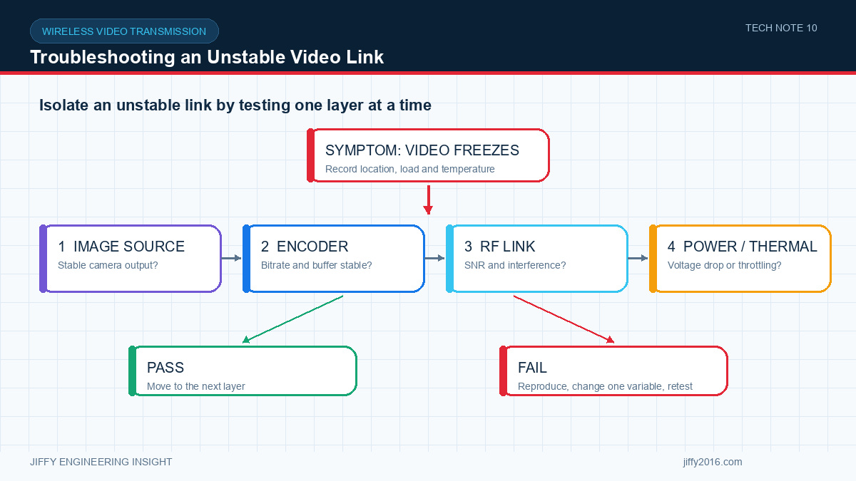
Quick answer: When a wireless video link keeps dropping, first determine whether the failure begins in the RF link, application network, codec, camera, power supply or temperature. Freeze the configuration, reproduce the failure at a known checkpoint and correlate video behavior with signal telemetry, throughput, packet loss, voltage, current and temperature.
A frozen picture does not prove that the radio disconnected. The camera may stop producing frames, the encoder may stall, a network queue may overflow or the receiver application may fail to restart. Troubleshooting is fastest when the complete chain is separated into observable stages.
- Key Takeaways
- Reproduce the problem before changing settings.
- Identify the first stage that fails.
- Correlate RF, traffic, codec, power and thermal logs.
- Change one variable at a time.
- Test recovery, not only the moment of failure.
- Freeze the configuration
- Is the camera still producing frames?
- Is the encoder or decoder overloaded?
- Is application throughput exceeding capacity?
- Check antennas and the propagation path
- Survey interference
- Check power and thermal behavior
- Examine reconnection logic
- Diagnostic sequence
- FAQ
- Why is signal level high while video still freezes?
- Should bitrate always be reduced first?
- Why does the link fail only after several minutes?
- Conclusion
Record frequency, bandwidth, power, antennas, cables, video format, codec, bitrate, network settings, firmware and application version. Photograph antenna mounting and note the exact failure location or condition.
Without this record, different tests may be comparing different systems.
Check camera status, frame counters and local preview if available. Inspect connector seating, cable length, exposure behavior and sensor temperature. A camera or interface fault can look like a radio failure at the remote display.
Observe processor load, memory, queue depth, dropped frames and codec logs. High-motion or high-detail scenes can increase variable bitrate. Confirm that the encoder, radio path and decoder are tested with the same demanding content.
If several streams are active, disable them one at a time to identify capacity limits without changing the RF configuration.
Compare sustainable application throughput with combined video, data and protocol overhead. Short traffic peaks may overflow buffers even when the average appears acceptable.
Reduce bitrate temporarily as a diagnostic. If stability improves, investigate traffic headroom, channel conditions, prioritization and buffering rather than treating the reduced rate as the final fix.
Inspect polarization, cable loss, connector condition, nearby metal and antenna shadowing. Repeat the failure with known antenna positions and at a clear short-range checkpoint.
If the short-range baseline fails, focus on hardware, configuration, interference close to the equipment, power or temperature. If only route sections fail, map obstruction, reflections and orientation.
Observe the intended band at representative times and locations. Interference may be intermittent or linked to machinery, other radios or site activity. Try a permitted alternate channel while keeping other settings fixed.
Do not increase transmit power before confirming regulations, antenna limits and the real cause. More power cannot repair a receiver blocked by strong in-band interference or a poor antenna installation.
Measure voltage at the transmitter, receiver and camera during the failure. Observe current and temperature. A supply drop during transmit peaks or a thermal reduction after several minutes can create repeated disconnects.
Repeat the test with the final enclosure closed and all simultaneous loads active.
Record which component detects failure and which component initiates recovery. The radio may reconnect while the video stream remains stopped. Define timeouts, retry limits, decoder reset and application state after network return.
Test temporary blockage, transmitter restart, receiver restart and camera restart separately. Each event may need a different recovery path.
1. Reproduce at a known location.
2. Confirm local camera output.
3. Check encoder frame and bitrate counters.
4. Check radio link and application throughput.
5. Check receiver network and decoder state.
6. Correlate voltage, current and temperature.
7. Change one variable and repeat.
8. Verify automatic recovery and long-duration stability.
Signal level does not describe codec load, throughput peaks, packet loss, camera health or application recovery. Check the full chain.
It is a useful diagnostic, but the final setting should still meet image requirements. Identify whether the true constraint is RF capacity, interference, encoder load or buffering.
Thermal rise, memory growth, storage behavior, power-converter heating or periodic interference may appear only after sustained operation.
An unstable video link is solved by locating the first failed stage and proving the cause with correlated evidence. Treat camera, codec, RF, network, power, thermals and recovery as one observable chain.
Discuss your system requirements with Jiffy
market@jiffy2016.com | www.jiffy2016.com
Subscribe to Our Newsletter
Your Email*
*Country*
*Verification code