How Antenna Height and Orientation Affect a Mobile Video Link
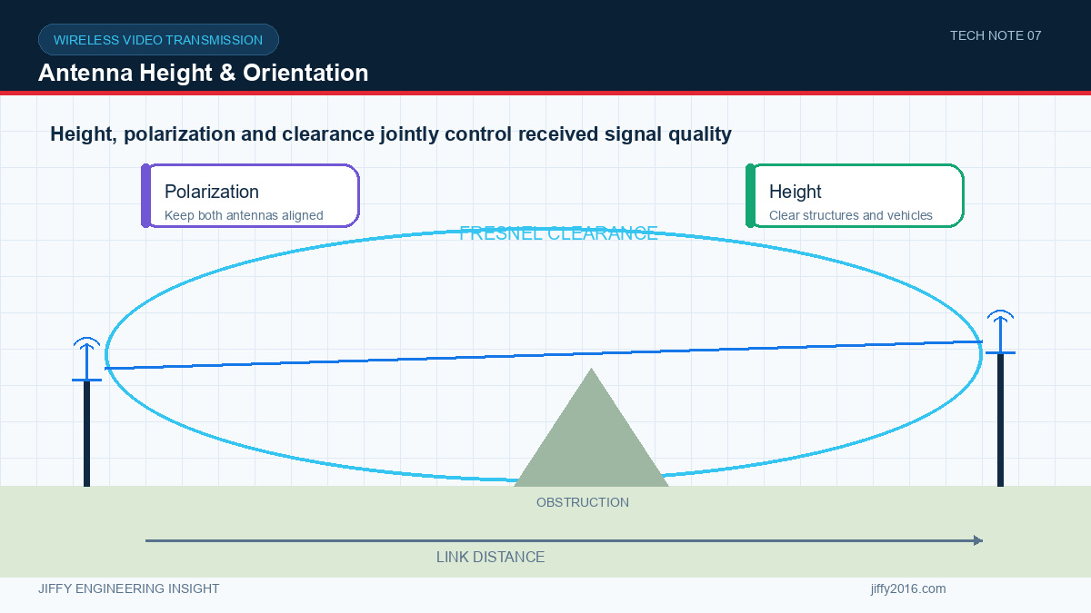
Quick answer: Antenna height and orientation affect wireless video by changing path clearance, polarization alignment, multipath and blockage from equipment or terrain. Raising a fixed antenna can improve clearance, but mobile antennas must also tolerate rotation and tilt. The best installation is confirmed with the actual antennas, cables, mounting surfaces and route.
A radio can meet its bench specification and still produce an unstable field link when antennas are installed behind metal, close to noise sources or with mismatched polarization. Antenna placement is part of the RF system, not a cosmetic decision made after the enclosure is complete.
- Key Takeaways
- Path clearance can matter more than a small increase in transmit power.
- Polarization mismatch reduces received signal even when distance is unchanged.
- Mobile rotation and tilt must be included in the antenna choice.
- Cable and connector losses can remove the benefit of higher antenna gain.
- Validate the final installation over the real route.
- Why does antenna height change performance?
- What is polarization alignment?
- How does nearby metal affect the antenna?
- Why are cable and connector losses important?
- Directional or omnidirectional antenna?
- Practical installation review
- Identify the antenna reference plane and intended polarization.
- Keep the radiating section clear of metal and noisy electronics.
- Record cable type, length, connectors and adapters.
- Check strain relief, sealing and vibration resistance.
- Confirm the antenna cannot be shadowed by moving parts.
- Test the complete range of mobile orientation.
- Evaluate both ends of the link; a strong base antenna cannot fix every mobile blockage.
- Field-validation method
- FAQ
- Should both antennas be mounted as high as possible?
- Can a higher-gain antenna solve orientation problems?
- Is received signal level enough to approve the installation?
- Conclusion
Height can reduce blockage by vehicles, machinery, people, vegetation or site structures. It can also improve clearance around the direct propagation path. A fixed control station often benefits from an elevated antenna because it has a stable position and can use a mast or building mount.
Height is not automatically better in every environment. It may expose the antenna to other interference sources, increase cable length or create a different reflection pattern. Evaluate the complete installation rather than using height as the only variable.
Polarization describes the orientation of the electric field. Two linearly polarized antennas normally perform best when their polarization is aligned. If one is vertical and the other is horizontal, the link can lose substantial margin.
A mobile platform may turn, lean or move over uneven surfaces. A fixed linear antenna that is ideal in one orientation may become poorly aligned in another. Diversity, suitable antenna geometry or multiple mounting positions can improve orientation tolerance, but each option must be tested with the selected radio.
Metal can block radiation, reflect energy and change antenna impedance. Mounting an antenna close to a chassis edge, battery, heatsink, camera housing or cable bundle can alter its pattern and matching.
Use the antenna manufacturer’s required ground plane and clearance guidance when available. Test the antenna on the production enclosure, because a free-space antenna measurement does not represent the installed condition.
Longer coaxial cable adds insertion loss. Small connectors, adapters and damaged assemblies can add further loss or mismatch. At higher frequencies, these effects can become more significant.
Choose the antenna location and cable route together. A high-mounted antenna connected through an unnecessarily long or unsuitable cable may deliver less system benefit than a closer antenna with a lower-loss path.
A directional antenna can increase gain toward a known area and reduce reception from other directions. It suits a fixed station when the operating sector is controlled. An omnidirectional antenna supports changing azimuth but normally has a broader pattern and different vertical coverage.
The words “directional” and “omnidirectional” do not fully describe coverage. Review the radiation pattern and confirm that the expected height differences and movement remain inside useful coverage.
Create a route with repeatable checkpoints. At each point, record antenna positions, orientation, frequency, bandwidth, power, video bitrate, link-quality telemetry and visible video behavior. Repeat the route after changing only one installation variable.
Test stationary and moving conditions, route reversals and turns. Include temporary blockage and recovery. A single maximum-distance result is less useful than a map of stable, marginal and failed areas.
Not automatically. Increase height when it improves clearance without creating excessive cable loss, mechanical risk or new interference exposure.
Higher gain often narrows part of the radiation pattern. It may improve one direction while reducing tolerance to tilt or height difference.
No. Also observe video continuity, application throughput, latency, packet loss and recovery because link-quality indicators do not describe the complete video chain.
The antenna installation defines how the wireless video system sees the operating environment. Plan height, polarization, cable loss, enclosure interaction and mobile orientation together, then validate them on the real route.
Discuss your system requirements with Jiffy
market@jiffy2016.com | www.jiffy2016.com
Subscribe to Our Newsletter
Your Email*
*Country*
*Verification code