A Field-Test Template for Wireless Video, Data and Recovery Performance
Quick answer: A useful wireless video field test records the complete configuration and measures more than maximum range. It should evaluate image quality, end-to-end latency, application throughput, link margin, route coverage, temporary blockage, reconnection, power stability and temperature using repeatable checkpoints and acceptance criteria.
Field testing should answer whether a defined system performs a defined task in a defined environment. A statement such as “the link reached the end of the site” cannot be compared later unless the radio, antennas, video settings, route and acceptance limits were recorded.
- Key Takeaways
- Freeze hardware, firmware and settings before the route test.
- Measure the application experience, not just radio telemetry.
- Test movement, blockage, traffic peaks and reconnection.
- Use repeatable checkpoints and synchronized logs.
- Record failed conditions as carefully as successful ones.
- 1. Write the acceptance criteria
- 2. Freeze the test configuration
- 3. Establish a bench baseline
- 4. Define route checkpoints
- 5. Test movement and orientation
- 6. Exercise blockage and recovery
- 7. Load video, data and control together
- 8. Monitor power and temperature
- Minimum test record
- Date, location and weather or indoor condition
- Complete hardware and software configuration
- Route map and checkpoint list
- Antenna models, cables, mounting and orientation
- Video and data traffic settings
- Baseline and checkpoint observations
- Blockage and recovery timing
- Power and temperature logs
- Photos, screen recordings and anomaly notes
- Pass/fail decision against written criteria
- FAQ
- Should maximum distance be the main result?
- How many times should the route be repeated?
- What should be changed when a test fails?
- Conclusion
Define the required video resolution, frame rate, maximum acceptable delay, number of streams, control traffic and recovery time. Describe what counts as a failure: frozen picture, excessive artifacts, delayed control response, lost data or manual reconnection.
Acceptance criteria should match the task. General observation and reading a small instrument display require different image performance.
Record transmitter, receiver, camera, firmware, frequency, bandwidth, power setting, modulation mode, antennas, cable lengths, video codec, bitrate and network settings. Photograph mounting and antenna orientation.
Use the same configuration for baseline and route comparison. If anything changes, create a new test record.
At short range, verify all video and data paths. Measure capture-to-display latency using a repeatable visual or timestamp method. Run the full number of streams and the intended return data.
Confirm that the system can operate continuously without network, codec, power or temperature errors before introducing path loss.
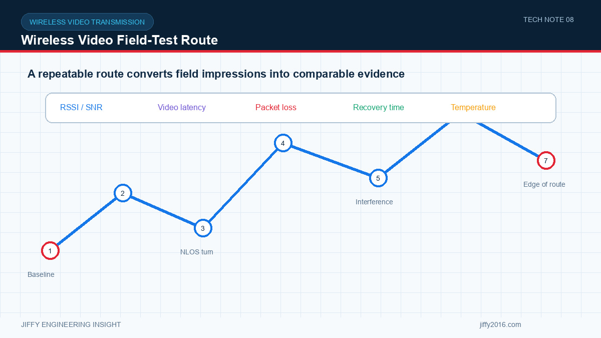
Mark locations that represent clear path, partial obstruction, turns, height changes, metal structures and known interference. Record distance or location in a form that can be repeated.
At each checkpoint, observe video, application throughput, latency, radio telemetry and any packet-loss or reconnect events. Do not rely on one averaged signal value.
Repeat the route at representative speed. Include turns, stops, reverse direction and changing antenna orientation. A stationary result may not show rapid fading or handover behavior caused by movement.
Use consistent camera scenes where possible, including motion and fine detail that create realistic encoder traffic.
Introduce temporary obstruction in a controlled, safe manner or use naturally obstructed route sections. Record how the system degrades, whether bitrate changes, when the picture freezes and how quickly it returns.
Also test receiver restart, transmitter restart and network interruption. Define whether the application must reconnect automatically and whether recording resumes correctly.
Run the maximum intended number of video streams plus telemetry, control and logging. Variable-bitrate video can create short peaks; record application throughput over time rather than only an average.
If control data has higher priority than video, verify that congestion behavior preserves the required response.
Record transmitter and receiver supply voltage, current and temperature during the route and a long stationary run. Enclosure temperature, sun exposure and low airflow can change performance after the short route is complete.
No. Stable coverage, latency, throughput and recovery over the required route are normally more useful than one best-case endpoint.
Repeat enough to expose variation in movement, orientation and site activity. At minimum, compare both travel directions and representative operating periods.
Change one controlled variable at a time—antenna position, channel, bandwidth, bitrate or power—then repeat the same checkpoint or route.
A good field test produces evidence that another engineer can reproduce. Define the task, freeze the configuration and measure route behavior, traffic, recovery, power and temperature as one system.
Discuss your system requirements with Jiffy
market@jiffy2016.com | www.jiffy2016.com
Subscribe to Our Newsletter
Your Email*
*Country*
*Verification code