Planning an Industrial Wireless Video Link - Why Range Is Not the Only Number
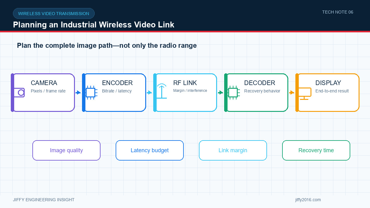
Quick answer: Planning an industrial wireless video link requires more than choosing a maximum range. Define the visual task, stream bitrate, end-to-end latency, recovery time, RF link budget, antenna installation, spectrum conditions and field-test method. Validate the complete camera-to-display path under representative motion, obstruction, traffic and temperature conditions.
A reliable video link is a chain: camera, encoder, radio, antenna system, propagation path, receiver, decoder, display and control network. A headline distance does not describe how that chain will behave in a factory, tunnel, port, vehicle or temporary field site.
- Key Takeaways
- Start with what the operator or software must see.
- Measure end-to-end latency rather than radio delay alone.
- Build a link budget with cable loss and fade margin.
- Survey the actual spectrum, path and antenna positions.
- Approve the link through repeatable bench and route tests.
- Begin with the image task
- Define acceptable latency and recovery
- Build a link budget
- Survey the spectrum and path
- Separate radio capacity from application throughput
- Validate in stages
- FAQ
- Why is a quoted wireless range not enough for system selection?
- How much throughput margin should a video link have?
- What should be recorded during a field test?
- Conclusion
Define what the operator or software must see. Navigation, general observation, reading a gauge and identifying a small defect need different resolution, frame rate and image quality. More video quality usually means a higher or less variable bitrate, which reduces RF margin or requires more channel capacity.
For several cameras, decide whether streams are simultaneous, selectable or combined. Include audio, telemetry, control and return data in the traffic model.
Latency should be measured from image capture to display or processing output. Camera exposure, image processing, compression, buffering, radio transport, decoding and display all contribute. A low radio delay cannot compensate for large buffers elsewhere.
Also define recovery behavior. How quickly should the picture return after a temporary obstruction or power interruption? Should the system reduce bitrate, change channel, reconnect automatically or alert the operator? These details often matter more than a best-case latency value.
A link budget combines transmit power, antenna gains, cable losses, propagation loss and receiver sensitivity. It should include a fade margin for movement, obstruction, orientation, interference and installation variation.
Do not assume both ends can use the same antenna. A fixed base station may support a directional or elevated antenna, while mobile equipment may need wide coverage and tolerance to changing orientation. Connector and cable losses can remove much of the benefit of a high-gain antenna if they are not controlled.
Industrial sites can contain access points, private networks, motors, variable-frequency drives, metal structures and moving vehicles. Measure the intended band at the actual site and at representative times. Map areas with obstruction, reflections or rapid changes in path geometry.
Line of sight is not a simple yes-or-no condition. Antenna height, nearby metal, path clearance and movement affect multipath and fading. A bench test across an open room is useful for baseline checks but does not replace a route test.
The physical-layer data rate is not the same as the sustainable application throughput. Protocol overhead, retransmissions, error correction and changing channel conditions reduce usable capacity. Leave headroom above the expected video and data load.
Variable-bitrate encoders can create short traffic peaks. Test high-detail and motion scenes, not only a static image. Confirm behavior when several streams, control traffic and logging run at the same time.
1. Bench baseline: verify interfaces, video format, bitrate, latency and continuous operation at short range.
2. Controlled attenuation: introduce repeatable RF loss or increase path distance while recording link quality and video behavior.
3. Representative route: test the real movement, antenna positions, obstacles and interference conditions.
4. Fault and recovery: block the path, interrupt power and generate traffic changes to confirm recovery behavior.
5. Thermal run: operate the complete system at the expected ambient temperature and duty cycle.
Record the model, firmware, frequency, bandwidth, power setting, antennas, cable lengths, camera format, encoder settings and environment. Without these details, a distance result cannot be reproduced.
Range depends on frequency, antenna installation, path clearance, interference, bitrate, receiver performance and acceptance limits. A distance without its test conditions cannot predict a specific site.
There is no universal percentage. Measure average and peak application traffic, include protocol overhead and retransmissions, then verify that the link remains stable during high-motion and high-detail scenes.
Record hardware and firmware versions, radio settings, antennas, cable lengths, camera and encoder settings, route, obstructions, spectrum conditions, throughput, latency, interruptions and recovery time.
Successful wireless video design balances image quality, latency, capacity, coverage, antenna installation, regulatory limits and recovery. Jiffy can help translate an operating route and video requirement into a defined evaluation kit and field-test plan.
Discuss your system requirements with Jiffy
market@jiffy2016.com | www.jiffy2016.com
Subscribe to Our Newsletter
Your Email*
*Country*
*Verification code