RF Power Amplifier Validation Checklist - From Bench Test to System Test
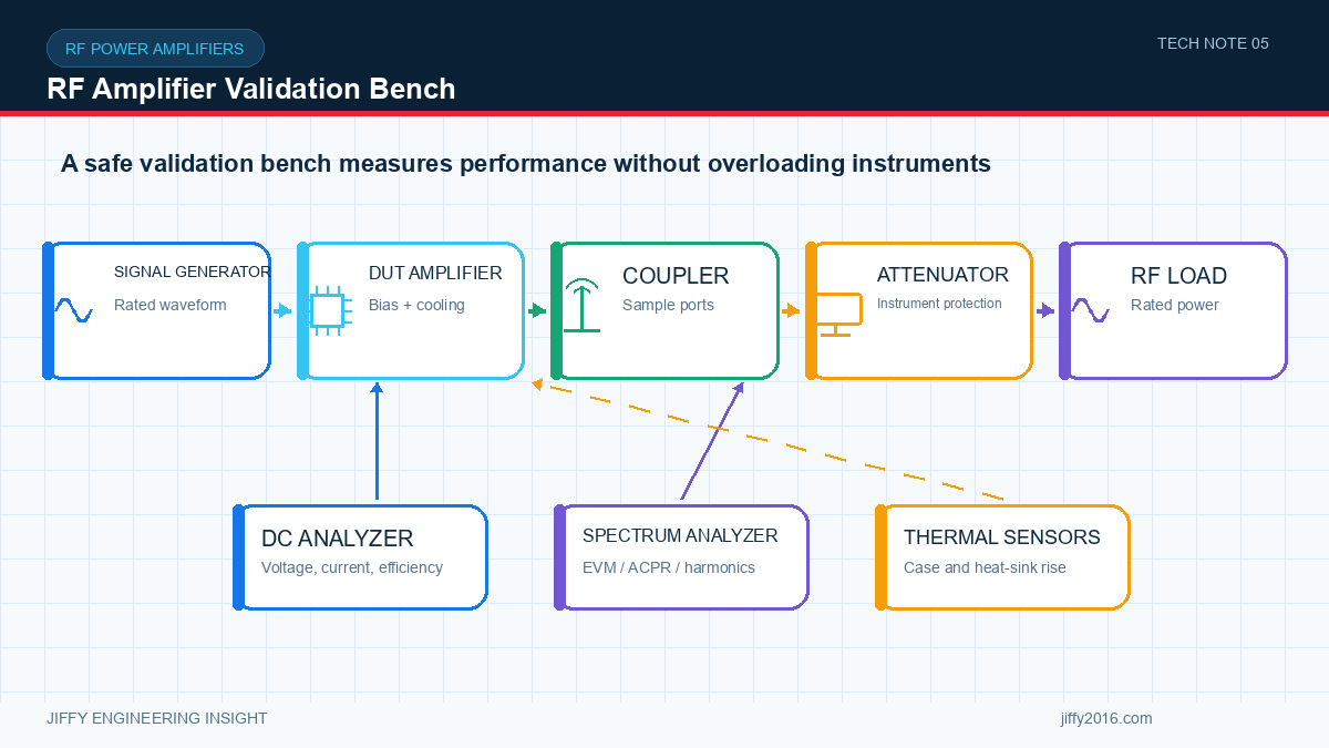
Quick answer: An RF power amplifier validation plan should verify the complete operating band, waveform quality, output power, harmonics, supply behavior, temperature, load mismatch, monitoring, protection and recovery. The test record must identify hardware, firmware, cables, instruments, settings and environmental conditions so results can be repeated.
A maximum-power measurement is not a complete RF amplifier qualification. Production readiness depends on repeatable behavior across frequency, power, waveform, supply, load and temperature—and on predictable recovery when conditions move outside the normal range.
- Key Takeaways
- Freeze the test configuration before comparing results.
- Validate signal quality and power together with the real waveform.
- Include the final filters, switches, cables and connector reference plane.
- Run long enough to expose thermal drift or protection behavior.
- Convert engineering tests into a smaller production acceptance test.
- 1. Define the configuration under test
- 2. Verify start-up and control behavior
- 3. Measure gain and output across frequency
- 4. Evaluate the real waveform
- 5. Confirm harmonics and filtering
- 6. Characterize the power input
- 7. Run the thermal profile
- 8. Test load mismatch safely
- 9. Exercise fault and recovery cases
- 10. Repeat with the host system
- Engineering test record
- Product model and serial or sample identifier
- Hardware, firmware and configuration versions
- Instrument models and calibration status
- Cables, adapters and measured losses
- Frequency, waveform, bandwidth and input level
- Output reference plane
- Supply and load conditions
- Ambient, airflow and enclosure state
- Raw data, summary and pass/fail limits
- Photos and notes for anomalies
- Production acceptance test
- FAQ
- How many frequency points should be tested?
- Is a 50-ohm bench load enough?
- When should testing be repeated?
- Conclusion
Record model, hardware revision, firmware, calibration version, frequency settings, gain or power commands, supply voltage and control interface. Identify every external filter, switch, cable, adapter, load and instrument.
Photograph the setup and state the RF reference plane. Without this baseline, a later result cannot be compared reliably.
Test normal power-up, enable, disable and shutdown sequences. Confirm default gain or power, telemetry availability and response to invalid or interrupted commands. Check behavior when the controller starts before or after the amplifier.
Repeat after a brownout and rapid restart within the product’s supported conditions. Configuration should return to the documented state or report a clear fault.
Measure small-signal or defined operating gain, gain flatness and output power at representative frequencies including band edges. Use input levels that match the intended radio chain.
Record cable and adapter losses. If power is controlled digitally, verify commanded steps and monotonic behavior at the final output reference plane.
Use the intended modulation or a representative waveform with the same bandwidth and peak behavior. Measure the applicable signal-quality metric and out-of-band energy while increasing output.
Identify the usable operating point, not only the saturated limit. Repeat at the frequencies and temperatures most likely to stress linearity.
Measure harmonics and other unwanted emissions with the intended production filtering installed. Inspect whether filter loss, switching or load variation changes delivered output or amplifier behavior.
Regulatory compliance requires a separately defined process; a development spectrum check does not by itself establish certification.
Measure minimum terminal voltage, average and peak current, ripple and transient recovery during start-up, transmit transitions and maximum expected duty cycle. Test with the production cable and connector path.
Check for interaction with other host loads. A processor, motor controller or video encoder may create supply changes that are absent from a standalone test.
Install the amplifier in the final mechanical stack, including interface material, chassis, enclosure and airflow. Operate the real waveform and duty cycle until temperatures stabilize.
Record output power, signal quality, current and temperatures over time. Note any throttling, gain change or protection event. Repeat at the target ambient condition and enclosure orientation.
Use appropriate equipment and procedures to introduce defined mismatch conditions. Verify forward and reflected monitoring, warning, power reduction, shutdown, retry and recovery.
Test both brief and sustained events within safe limits. Confirm fault reporting and whether a normal load can be restored without an uncontrolled output transition.
Include low supply voltage, overtemperature, control loss, detector error if supported, unexpected disable and power interruption. For each case, define the expected state, telemetry, log record and recovery method.
Protection is complete only when the host can understand what happened and the system returns to a known state.
Install the amplifier in the intended equipment and operate all simultaneous loads. Look for conducted or radiated interference, grounding problems, cable coupling, antenna detuning and thermal interaction.
Perform a representative route or site test when the product depends on a wireless link. Record antenna, channel, bandwidth, power and environment with every result.
The factory test does not need to reproduce every engineering experiment. Select a smaller set of measurements that detects assembly, calibration, interface and RF-path faults. Define fixtures, limits, software version and golden-sample control.
Use enough points to represent band edges, known response features and production risk. The number depends on bandwidth and design; do not assume center frequency is sufficient.
It establishes a controlled baseline but does not reproduce the final antenna, cable, switching and environment. Complete system validation is still required.
Repeat relevant tests after changes to hardware, firmware, calibration, filtering, supply, mounting, enclosure, antenna or operating waveform.
RF amplifier validation should demonstrate useful signal quality and predictable protection inside the complete product. A controlled, versioned test record turns a successful prototype into a repeatable engineering and production baseline.
Discuss your system requirements with Jiffy
market@jiffy2016.com | www.jiffy2016.com
Subscribe to Our Newsletter
Your Email*
*Country*
*Verification code