RK3576 Four-Camera Edge AI Board for Robot Obstacle Avoidance and Autonomous Navigation
How synchronized multi-camera vision and edge AI help mobile robots perceive obstacles, estimate pos
RK3576 Four-Camera Edge AI Board for Robot Obstacle Avoidance and Autonomous Navigation
Autonomous mobile robots need more than a single forward-facing camera. They must detect objects around the platform, estimate free space, understand motion and maintain localization while operating close to shelves, machinery, vehicles and people.
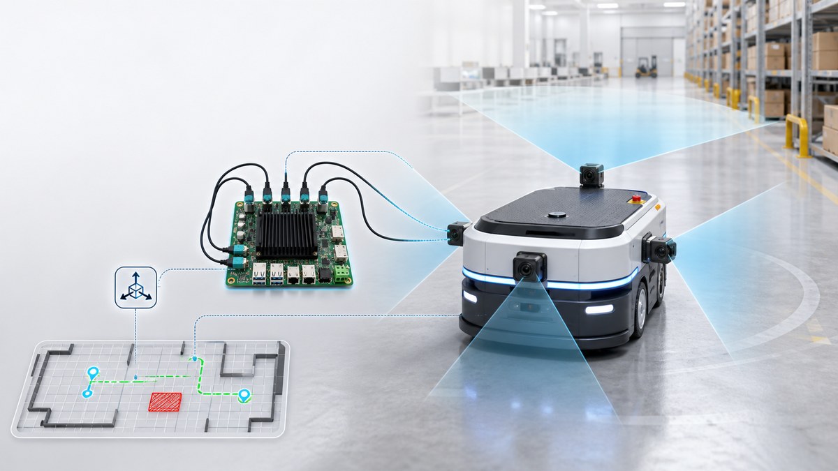
The Jiffy JAIDB-3576-4C is designed for this type of multi-camera visual perception. Based on the Rockchip RK3576 processor, the board integrates four independent MIPI camera interfaces, a high-precision IMU and hardware-level synchronization capabilities. It provides a practical computing foundation for obstacle avoidance, visual-inertial navigation and multi-directional environmental perception.
Why Use Four Cameras for Mobile Robot Perception?
A single camera can leave significant blind areas around a mobile platform. Four cameras can be arranged according to the vehicle structure and operating environment.
Typical configurations include:
One front camera for route perception and obstacle detection
One rear camera for reversing and docking
Two side cameras for lateral clearance and blind-area monitoring
Two front-facing cameras for stereo depth, plus two side or rear cameras
Four outward-facing cameras for near-360-degree environmental coverage
The correct arrangement depends on the required field of view, minimum detection distance, mounting height and vehicle dimensions.
Four-camera perception is especially useful for autonomous mobile robots, warehouse transport vehicles, inspection robots, cleaning robots, delivery platforms and compact ground vehicles operating in constrained environments.
Synchronized Vision and IMU Data
Multi-camera navigation requires more than simply connecting several image sensors. The frames must be aligned closely enough for the perception software to determine which observations occurred at the same moment.
The JAIDB-3576-4C supports four independent MIPI camera inputs and a hardware synchronization mechanism designed to improve temporal alignment between camera frames. Its integrated IMU provides acceleration and angular-motion data that can be fused with visual information.
This visual-inertial architecture can support:
Visual odometry
Visual-inertial odometry
SLAM localization
Motion estimation
Camera pose estimation
Short-term localization when visual features are limited
Detection of rapid changes in vehicle orientation
Accurate timestamps, camera calibration and stable mounting remain essential. Synchronization improves data quality, but it does not replace proper optical and mechanical calibration.
Edge AI Processing with RK3576
The RK3576 includes a 6 TOPS NPU for accelerating supported neural-network models. Instead of sending all camera streams to a remote server, the board can process visual data close to the cameras.
A typical perception pipeline may include:
Capturing synchronized images from four cameras
Correcting lens distortion and aligning camera geometry
Running object detection or semantic segmentation
Estimating depth or traversable space
Combining visual features with IMU measurements
Updating the local map and robot position
Sending perception results to the motion-planning controller
Edge processing reduces network dependence and allows the robot to react locally. It also helps keep large volumes of raw image data inside the machine.
Obstacle Avoidance Functions
A four-camera system can support several complementary obstacle-avoidance methods.
Object detection identifies known classes such as people, vehicles, pallets, boxes and equipment. Semantic segmentation separates floor, walls, machinery and other regions at pixel level. Stereo vision estimates distance when two cameras have suitable overlap and calibration. Optical flow helps measure image motion and relative movement.
These results can be converted into a local occupancy map or obstacle list for the navigation system.
The final stopping and steering decisions should be handled by a properly designed motion-control and safety architecture. For safety-critical equipment, cameras are commonly combined with lidar, ultrasonic sensors, bumpers, wheel encoders or emergency-stop circuits according to the project risk assessment.
Autonomous Navigation and SLAM
Obstacle detection answers the question, “What is near the robot?” Autonomous navigation must also answer, “Where is the robot, and where can it move next?”
The four-camera RK3576 platform can provide data for:
Visual SLAM in indoor facilities
Visual-inertial localization
Route following
Corridor and aisle navigation
Docking-station alignment
Marker or feature-based positioning
Map updating
Local path planning
In a warehouse, front and side cameras can monitor aisle boundaries while the rear camera supports docking. In an inspection robot, cameras can provide localization features while also recording equipment conditions. In a mobile service platform, panoramic perception can reduce blind areas around people and furniture.
Camera and Lens Selection
The computing board is only one part of the system. Camera selection directly affects obstacle-detection performance.
Important considerations include:
Global shutter versus rolling shutter
Resolution and frame rate
Low-light sensitivity
Horizontal and vertical field of view
Lens distortion
Minimum object-detection distance
Dynamic range
Camera synchronization support
Cable length and connector stability
Exposure consistency between cameras
Global-shutter cameras are often preferred for moving platforms because they reduce geometric distortion caused by motion. Wide-angle lenses improve coverage but require stronger distortion correction and careful calibration.
Integration Support from Jiffy
Jiffy can support board-level and system-level adaptation for multi-camera edge AI projects, including:
Camera sensor and lens selection
MIPI interface adaptation
Four-camera synchronization
IMU integration
Cable and connector customization
Linux, Ubuntu and embedded software environments
RKNN model conversion and deployment
Enclosure and thermal design coordination
Prototype evaluation and production support
Frequently Asked Questions
Can the RK3576 board process four camera streams simultaneously?
The JAIDB-3576-4C is designed with four MIPI camera inputs. Actual resolution, frame rate and AI-processing performance depend on the camera configuration, image-processing pipeline and deployed models.
Can four cameras provide 360-degree obstacle detection?
Four wide-angle cameras can provide extensive surrounding coverage, but the exact blind areas depend on lens field of view, mounting position, overlap and vehicle geometry. Coverage should be verified on the completed platform.
Can camera vision completely replace lidar?
Not in every application. Cameras provide rich visual information, while lidar can offer direct geometric distance measurements. Many safety-oriented systems combine cameras with lidar, ultrasonic sensors, bumpers or other independent sensors.
Conclusion
The Jiffy JAIDB-3576-4C provides a compact platform for four-camera perception, visual-inertial localization and edge AI processing. Its synchronized camera architecture, integrated IMU and 6 TOPS NPU make it suitable for AMRs, AGVs, inspection robots and other autonomous ground systems that require responsive local perception.
Contact Jiffy to discuss camera layout, sensor selection, synchronization, AI model deployment and hardware customization for your navigation project.
Subscribe to Our Newsletter
Your Email*
*Country*
*Verification code