RF Output Back-Off - Why Saturated Power Is Not Usable Linear Power
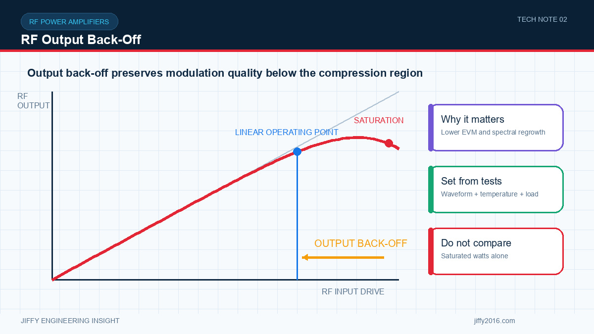
Quick answer: RF amplifier output back-off is the reduction between an amplifier’s maximum or saturated output and the lower operating power used to preserve signal quality. The required back-off depends on waveform peak-to-average ratio, linearity targets, bandwidth, temperature, gain variation and the system’s EVM or spectral-mask limits.
An RF power amplifier may be capable of producing a high saturated output, but a digitally modulated signal often cannot use that level without unacceptable distortion. Output back-off creates operating margin between the amplifier’s nonlinear region and the signal peaks that must pass through the chain.
- Key Takeaways
- Saturated power describes a device limit, not necessarily useful system power.
- Waveforms with larger signal peaks generally need more linear operating margin.
- Back-off must be verified with the real waveform, bandwidth and filtering.
- EVM, adjacent-channel energy and thermal behavior should be measured together.
- A single back-off value should not be copied between different bands or configurations.
- What does output back-off mean?
- Why does the waveform change the answer?
- Which measurements define usable power?
- Error vector magnitude or another modulation-quality metric
- Adjacent-channel or out-of-band energy
- Gain compression and gain flatness
- Harmonics after the intended filtering
- Current consumption and power-supply stability
- Case temperature and protection behavior
- Performance across frequency and ambient temperature
- How should input drive be controlled?
- Why do filtering and load matter?
- How does temperature affect back-off?
- Recommended evaluation method
- Common mistakes
- Treating saturated power as the normal continuous output
- Using a tone test to approve a modulated application
- Quoting back-off without naming the reference point
- Measuring before the final filter or cable path
- Ignoring warm-state performance
- Setting power only from a software value without connector measurement
- FAQ
- Is output back-off the same as gain reduction?
- Can one back-off value be used for every modulation?
- Does more back-off always improve the system?
- Conclusion
Output back-off is normally expressed as the difference between a reference maximum output and the actual average operating output. The reference might be saturated power, a specified compression point or another defined linearity boundary. The reference must be stated because different definitions produce different numbers.
The purpose is not simply to reduce power. It is to give the amplifier enough headroom to reproduce peaks without severe compression, clipping or phase distortion. That headroom helps the transmitted signal remain within system quality and emission limits.
A constant-envelope waveform presents a different load to the amplifier than a signal with large amplitude variation. Modern modulated signals can have an average level that appears moderate while short peaks approach the amplifier’s nonlinear region.
The peak-to-average relationship depends on modulation, channel bandwidth, filtering and traffic. Test signals must represent the real application. A continuous tone can confirm gain and maximum output, but it cannot by itself demonstrate how the amplifier will handle a complex waveform.
Usable output power is the highest operating level that satisfies all relevant acceptance criteria. Depending on the system, these may include:
The limiting measurement may change with frequency. One part of the band may be limited by gain flatness, another by filtering, and another by temperature or signal quality.
The amplifier cannot maintain a defined output if the input chain is not controlled. Calculate the available drive from the radio through switches, attenuators, filters, cables and connectors. Include tolerance, temperature and frequency variation.
If the platform supports adjustable gain or power control, define the control range, step behavior, start-up setting and response to invalid commands. Confirm that a control fault cannot unintentionally overdrive the amplifier.
The amplifier is only one part of the RF path. Filters can add loss, alter group delay or interact with the load presented to the output stage. Antenna mismatch and cable variation can change delivered power and reflected energy.
Measure the complete path at the final connector whenever possible. A clean result measured before the production filter does not prove that the assembled transmitter will meet its target.
Gain, efficiency and linearity can change as the amplifier heats. A setting that passes during a short cold test may fail after the enclosure reaches thermal equilibrium. The back-off decision should therefore include the expected duty cycle, airflow, mounting and ambient temperature.
Monitor supply voltage, current, case temperature and any internal telemetry during the test. If protection repeatedly reduces power during normal use, the system needs a thermal or operating-point change rather than a different software threshold.
1. Define the target band, waveform, bandwidth and output connector.
2. Record the reference maximum-power definition.
3. Set the intended input chain and production filtering.
4. Sweep operating output while measuring signal quality and emissions.
5. Repeat at band edges and representative frequencies.
6. Run the expected duty cycle until temperature stabilizes.
7. Repeat under supply and load conditions expected in the host system.
8. Select an operating point with margin for production tolerance and environment.
Not necessarily. Gain reduction may be one method of achieving a lower output, but output back-off describes the difference between a defined maximum reference and the actual operating output.
No. Waveform peaks, bandwidth and signal-quality requirements differ. Validate the actual or a technically representative waveform.
More margin can improve linearity, but it also reduces delivered power and may reduce link margin. The correct point satisfies signal quality, emissions, coverage and thermal requirements together.
RF output back-off is a system decision, not a fixed percentage taken from a data sheet. Define the waveform and acceptance limits, measure the complete RF path under warm operating conditions and select an output with documented margin.
Discuss your system requirements with Jiffy
market@jiffy2016.com | www.jiffy2016.com
Subscribe to Our Newsletter
Your Email*
*Country*
*Verification code