Selecting an RF Power Amplifier - Seven System Questions to Answer
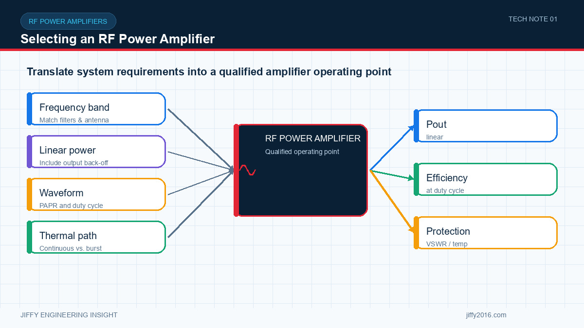
Quick answer: To select an RF power amplifier, define the operating band, waveform, linear output requirement, available drive, duty cycle, load mismatch, interfaces and thermal environment before comparing products. The correct amplifier is the one that meets signal-quality and reliability targets in the complete RF chain, not simply the model with the highest saturated output.
An RF power amplifier cannot be selected from frequency and output power alone. The amplifier sits inside a signal chain, and its useful performance depends on the waveform, drive level, filtering, load, temperature, duty cycle and regulatory limits of the complete system.
- Key Takeaways
- Define the waveform and usable linear power, not only saturated output.
- Calculate gain and drive margin across the complete RF path.
- Match thermal design to the real duty cycle and enclosure.
- Plan protection for reflected power, temperature and supply faults.
- Approve the amplifier with the final filters, cables, antenna and control logic.
- 1. What frequency range must the system cover?
- 2. What waveform and linearity are required?
- 3. How much gain and drive margin are available?
- 4. What is the real duty cycle?
- 5. What load conditions can occur?
- 6. Which interfaces and mechanics fit the host system?
- 7. What must be demonstrated before production?
- Gain and output across the required frequency range
- Signal quality at the intended waveform and operating power
- Harmonics and out-of-band emissions with the final filtering
- Current consumption and power-supply transient behavior
- Temperature rise at the expected duty cycle and ambient condition
- Response to load mismatch, overtemperature and low supply voltage
- Control-interface and telemetry behavior
- Recovery after power interruption or protection events
- FAQ
- Is the highest RF output power always the best choice?
- Why should the real waveform be used during evaluation?
- What information should be sent to an amplifier supplier?
- Conclusion
Start with the actual operating band, not a broad category name. A wideband platform can simplify product planning, but a narrower design may provide better efficiency or filtering for a fixed application. Confirm whether the amplifier must cover one continuous band, several separated bands or multiple country-specific configurations.
Frequency planning also affects connectors, filters, antennas, cables and test equipment. A change in one component can alter insertion loss, gain flatness and the available margin at the antenna port.
Constant-envelope and high-peak-to-average waveforms place different demands on an amplifier. Digital modulation may require output back-off so the signal remains within the target error-vector magnitude, spectral-mask or adjacent-channel limits. The maximum saturated power is therefore not always the useful operating power.
Share the waveform, bandwidth, expected peak-to-average ratio and required linearity. If these are still being defined, plan an evaluation that measures output power and signal quality together.
The output stage must receive sufficient input power without being overdriven. Calculate the signal chain from the radio output through switches, filters, cables and connectors. Include variation over frequency, temperature and production tolerance.
A controlled gain range or serial interface may help one platform serve several configurations. Confirm what happens during start-up, shutdown, loss of control and invalid commands.
A short burst test and continuous operation create very different thermal conditions. Define transmit duration, repetition rate, ambient temperature, airflow and enclosure restrictions. Include the heat produced by nearby electronics, not only the amplifier.
Thermal protection can prevent damage, but it does not replace thermal design. The production system should maintain the required RF performance without repeatedly entering protection under normal operation.
A disconnected, damaged or poorly matched antenna can reflect energy toward the amplifier. Review the required tolerance to voltage standing-wave ratio, reflected power and temporary load faults. Forward-power, reflected-power, current and temperature monitoring may be useful for control and diagnostics.
The protection strategy should define the response: warning, power reduction, shutdown, retry or manual recovery. Validate the behavior with the intended cables, connectors, antenna and switching sequence.
Confirm input voltage, peak current, enable logic, control interface, telemetry, connector orientation, mounting, heatsink contact and service access. A mechanically convenient amplifier can reduce cable loss and thermal resistance, but it must also be protected from interference generated elsewhere in the equipment.
For an embedded design, document grounding, shielding and the boundary between the amplifier and host enclosure. For an enclosed unit, define ventilation, mounting position and external connector requirements.
A useful validation plan includes:
Record the exact hardware, firmware, cables, instruments and settings. This baseline makes field results easier to interpret and future version changes easier to manage.
No. Useful output is limited by the required waveform quality, emissions, power supply, thermal path and load conditions. A lower operating point with documented margin is often more reliable.
Different waveforms create different peak levels and linearity demands. A single-tone test cannot demonstrate the EVM, spectral behavior or heat generated by the intended modulated signal.
Provide the frequency range, waveform, bandwidth, target connector power, available input drive, duty cycle, supply, control interface, mechanical limits and expected ambient temperature.
The right amplifier is the one that delivers the required signal quality and reliability inside the complete system—not simply the highest number on a specification table. Jiffy can help compare frequency, gain, power, monitoring, interfaces, mechanics and thermal requirements and define a testable evaluation configuration.
Discuss your system requirements with Jiffy
market@jiffy2016.com | www.jiffy2016.com
Subscribe to Our Newsletter
Your Email*
*Country*
*Verification code